Spider Glazing Systems use point-fixed fittings to support glass panels while keeping conventional framing visually discreet. That matters. A clear façade can bring daylight into a lobby, open views toward the street, and make an entrance feel lighter. But the refined appearance depends on careful engineering, not attractive hardware alone. Wind loads and glass weight must transfer through the fittings into a suitable supporting structure. Connection positions, glass thickness, edge distances, movement, and installation tolerances all need coordinated review. Small details show.
This approach can suit atriums, canopies, and public-facing façades where transparency is a design priority. It can also leave more glass edges and fittings exposed, making cleaning access, drainage, replacement methods, and weather performance important from the outset. Those questions are practical. Yet they are sometimes left too late. A framed façade may be a better fit where access is difficult, budgets are tight, or thermal targets are demanding. Compare long-term maintenance needs, not only the first impression. Ask qualified project professionals and suppliers for project-specific calculations, relevant tested details, and clear installation guidance. A full-scale mock-up can help reveal reflections, fitting visibility, and alignment issues before installation. Still, no system choice removes the need for site-specific assessment. The right decision depends on the building, its supporting structure, and the people who will maintain it.
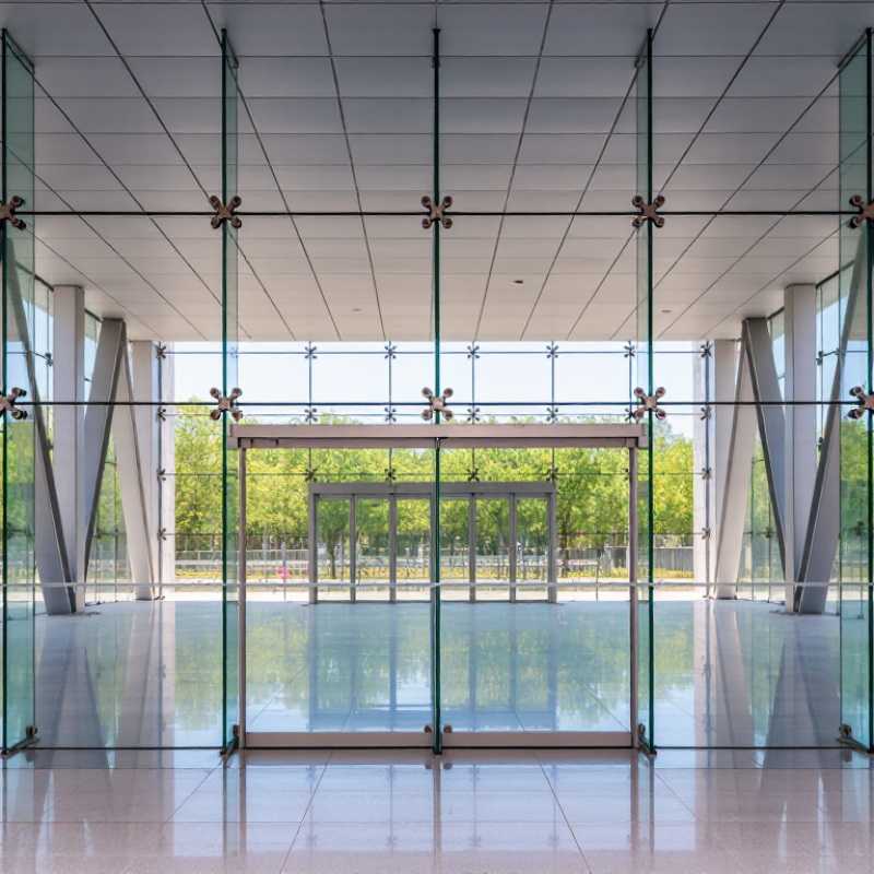
Spider glazing holds glass panels with discrete point fixings instead of continuous vertical and horizontal mullions. This creates open sightlines and lets daylight travel deeper into a room. The glass still needs a carefully engineered support path. Loads pass through fittings into a supporting structure, which may be a steel frame, glass fin, or another designed element. Every connection matters.
A typical panel has prepared holes for its fittings, while articulated connections can accommodate some movement. The exact detail depends on panel size, wind pressure, edge distances, and the structure behind it. Installation tolerances are tight. A small alignment error can leave uneven gaps or unwanted stress. This system can look remarkably light, but it is not automatically simpler or cheaper than framed glazing. That is easy to overlook. Cleaning access and replacement methods also deserve attention before drawings are finalized. Even experienced teams can discover awkward access only after the surrounding space is built.
Tips: Request structural calculations and a full-size connection detail early. Confirm how each panel can be safely reached and replaced. Check glass edges and fittings together, not as separate items. A mock-up can reveal reflections, joint widths, and small visual quirks before installation.
Spider glazing uses discrete point-fixings to support glass, rather than continuous mullions. This chart compares those defining support features; actual structural designs depend on project requirements.
Spider glazing keeps the façade visually open, but its performance depends on a clear load path. Wind pressure and the glass’s own weight move through several connected parts. Loads pass from each panel into its fittings, then into a supporting frame or structure. Small components, such as stainless-steel bolts and setting blocks, still matter.
Fittings transfer concentrated forces at carefully positioned points. Their stiffness, connection details, and distance from the glass edge affect local stress. The glass must be specified for the panel size, support arrangement, and expected loading. Deflection matters, too. A panel that bends excessively can place extra pressure on its fittings or nearby joints. Those effects need engineering checks, not visual guesses.
The supporting structure receives the combined loads and carries them into the building. It must be stiff enough to limit movement while allowing for temperature changes and construction tolerances. That detail is easy to underestimate. If the frame shifts, even slightly, the fittings may not share forces as intended. Designers should coordinate glass calculations, connection design, and structural drawings early, then verify installation conditions on site. A neat façade can conceal a weak load path; clear documentation and careful inspection help reveal it.
| Load-Path Stage | Typical Component | How Loads Are Transferred | Key Design Considerations |
|---|---|---|---|
| 1. Applied load | Glass façade panel | Wind pressure and suction act across the exposed glass surface. The panel bends and transfers reactions toward its point-support locations. | Panel dimensions, glass build-up, support layout, edge conditions, and project-specific design loads influence glass stresses and deflection. |
| 2. Panel response | Monolithic or laminated safety glass | The glass carries the applied surface load to the supported points. In laminated glass, the interlayer helps retain fragments after breakage; its structural contribution depends on material, temperature, and loading duration. | Check glass strength and deflection, hole geometry, edge quality, and the effects of temperature and interlayer properties where relevant. |
| 3. Point connection | Bolts, sleeves, or articulated connectors at glass holes | Fittings transfer concentrated reactions between the glass and the spider arms. Articulated details can accommodate limited movement or rotation when specifically designed to do so. | Glass holes create local stress concentrations. Connection design should account for bearing, clearances, contact materials, installation tolerances, and possible restraint forces. |
| 4. Load distribution | Spider fitting or point-support assembly | The fitting collects reactions from supported panels and passes them into its central connection or bracket. The force distribution depends on the geometry and stiffness of the assembly. | Verify fitting strength, stiffness, connection details, corrosion resistance, and compatibility with the specified movement and exposure conditions. |
| 5. Secondary support | Bracket, fin, mullion, or supporting frame | The support receives forces from the fittings and carries them to the primary structure. Depending on the arrangement, members may experience bending, shear, axial force, or torsion. | Assess member capacity and deflection, connection eccentricity, stability, and interactions with adjacent façade components. |
| 6. Primary structure | Structural steel, concrete, or other designed substrate | Anchors and structural connections transfer the façade reactions into the building structure, which carries them through its designed load path. | Check anchor capacity, embedment or attachment details, substrate condition, local reinforcement, and the structure’s ability to resist the applied reactions. |
| 7. Serviceability and movement | Glazing joints, seals, and movement details | Joints accommodate specified thermal movement, building movement, and construction tolerances while maintaining the intended weather and air seals. | Coordinate joint widths, sealant selection, drainage, movement capacity, and interfaces with adjacent façade systems. |
Note: This is a typical load-path overview, not a project-specific design. Actual loads, glass make-up, fitting arrangement, anchorage, and structural checks must be determined for the project by qualified façade and structural professionals in accordance with applicable codes and standards.
Wind pressure is a project input, not a standard value to copy between façades. ASCE/SEI 7-22 derives design wind loads from location, building height, exposure, and risk category. As a rough reference, q = 0.613V² gives about 0.98 kPa at 40 m/s. That is velocity pressure only, not the final pressure on a glass panel; exposure and other design factors still apply. Small changes matter. Confirm both positive and negative pressures before fixing panel sizes or spider fittings.
Panel dimensions affect glass stress and deflection, while support geometry influences how loads reach the fittings. ASTM E1300-16a(2021) provides methods for assessing glass resistance under specified loads, dimensions, support conditions, and load duration. Use it to check the proposed glass type and make-up, rather than treating thickness alone as proof of capacity. A large panel may look clean on drawings, yet its edges and connection zones deserve close review.
Glass build-up should follow the structural checks and the project’s safety and performance needs. Laminated glass can retain fragments after breakage, but its interlayer and plies must be specified for the actual design conditions. Thermal and acoustic targets may also change the make-up, sometimes adding weight. Record the design pressures, panel dimensions, glass layers, interlayer, and support details together. One detail is easy to miss: confirm tolerances and edge clearances with the fabricator before the final schedule is issued.
Spider glazing relies on small fittings, drilled holes, and carefully managed glass edges. These details make structural checks essential. ASTM E1300 provides procedures for evaluating glass resistance under specified loads, using factors such as glass type, dimensions, support conditions, and load duration. It is a calculation practice, not a physical test or a blanket approval for every spider-supported panel.
For point-supported glass, engineers should compare project wind pressures with the panel’s calculated capacity and examine stresses around holes and fittings. The design pressure should come from the project’s adopted wind-load criteria, not a convenient rule of thumb. A thin panel may meet a general load check yet still need closer review at its fixings. Small details matter.
Water performance needs a separate check. ASTM E1105 evaluates installed windows, doors, and curtain walls under controlled water spray and pressure difference. Its spray rate is 5.0 U.S. gallons per square foot per hour, about 3.4 liters per square meter per minute. The test pressure is set by the project specification; the standard does not prescribe one universal pass pressure. Testing a representative installed assembly can reveal leakage at joints, gaskets, or penetrations that drawings miss. It can be awkward to discover late. That is exactly why early mock-up testing is worth considering.
Spider glazing uses compact point fixings instead of broad frames, keeping sightlines open across entrances, atriums, and glazed façades. The effect is immediate. From inside, you see less metal and more of the exterior. Daylight can reach deeper into a lobby, though glare and solar heat still depend on orientation, glass selection, and shading.
The clean appearance comes with structural demands. Loads travel through fittings and supporting steel or concrete, so the connections need careful engineering. Glass panels also require suitable edge distances and drilled-hole details; small installation errors can create stress around the fixings. This system is not automatically the lightest or simplest option. A narrow mullion can sometimes provide a more forgiving solution, especially where the structure moves or tolerances are uncertain.
Maintenance deserves attention before drawings are finalized. Spider fittings, gaskets, and sealant joints need periodic inspection, particularly after severe weather or nearby construction. Dust and water marks show readily on exposed glass, and safe access may require lifts or planned façade equipment. Cleaning is manageable. Replacing a damaged panel is less so. Ask how crews will reach each fixing, and whether the glass can be removed without disturbing adjacent panels.
Location, building height, exposure, and risk category all matter. A 40 m/s wind gives roughly 0.98 kPa velocity pressure. Not the final panel load.
They can load the panel in different directions. Confirm both before fixing panel sizes or fittings.
Larger panels can change glass stress and deflection. Support locations also affect how loads reach the fittings. Edges need close review.
No. Capacity depends on glass type, dimensions, supports, and load duration. Check the proposed glass make-up against project loads.
It can help retain fragments after breakage. Specify its plies and interlayer for the design conditions. The added weight may matter.
Point supports can create stress around holes and connection zones. A general load check may not settle those local questions. Small details matter.
It checks an installed assembly under water spray and pressure difference. Leakage may appear at joints, gaskets, or penetrations.
No. The project specification sets the test pressure. The spray rate is about 3.4 liters per square meter per minute.
Consider testing a mock-up early, before installation details are final. Late leakage discoveries are awkward. I would still verify edge clearances with the fabricator.
Spider Glazing Systems use point-fixed fittings to support glass without continuous mullions, creating open façades with clear sightlines and generous daylight. Their performance depends on a carefully designed load path: wind forces move from each glass panel through its fittings and into the supporting structure. Choosing a suitable system therefore requires attention to local wind pressure, panel size, glass build-up, and the strength and movement of the structure.
Design checks should confirm that the glass can resist the required loads, including evaluation in accordance with ASTM E1300, and that the façade can meet water-resistance requirements, including testing to ASTM E1105. These systems can offer a light, transparent appearance, but they also involve trade-offs. Point supports and exposed glass may require thoughtful detailing, regular inspection, and ongoing cleaning and maintenance. Balancing appearance, performance, and upkeep early helps ensure the system suits the project.